- 您现在的位置:买卖IC网 > Sheet目录19096 > LD400600 (Red Lion Controls)COUNTER 6 DIGIT 4.0" 120VAC RED
�� �
�
�2.0� S� ETTING�
�THE�
�DIP� S� WITCHES�
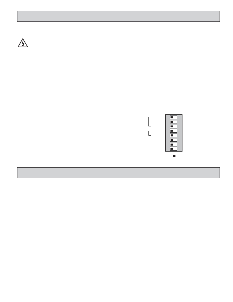
�SETTING� THE� 8� DIP� SWITCHES�
�To� access� the� switches,� remove� the� right� side� plate� of� the� meter.� A� bank� of�
�eight� switches� is� located� inside� the� unit.�
�Warning� :� Exposed� line� voltage� exists� on� the� circuit� boards.�
�Remove� all� power� to� the� meter� and� load� circuits� before� accessing�
�inside� of� the� meter.�
�SWITCH� 1� (Input� A)�
�LOGIC� :� Input� A� trigger� levels� V� IL� =� 1.25� V� max.;� V� IH� =� 2.75� V� min.;�
�V� MAX� =� 28� VDC�
�MAG� :� 200� mV� peak� input� sensitivity;� 100� mV� hysteresis;� maximum� voltage:�
�40� V� peak� (28� Vrms);� Must� also� have� SRC� switch� ON.� (Not� recommended�
�with� counting� applications.)�
�SWITCH� 2� (Input� A)� {See� Note� 1}�
�SNK� .:� Adds� internal� 7.8� K� ?� pull-up� resistor� to� +12� VDC,� I� MAX� =� 2.1� mA.�
�SRC� .:� Adds� internal� 3.9� K� ?� pull-down� resistor,� 7.2� mA� max.� @� 28� VDC� max.�
�SWITCH� 3� (Input� A)�
�HI� Frequency� :� Removes� damping� capacitor� and� allows� max.� frequency.�
�LO� Frequency� :� Adds� a� damping� capacitor� for� switch� contact� bounce.� Limits�
�input� frequency� to� 50� Hz� and� input� pulse� widths� to� 10� msec.�
�SWITCH� 6� (RESET/USER� INPUT)� {See� Note� 1}�
�SNK� .:� Adds� internal� 7.8� K� ?� pull-up� resistor� to� +12VDC,� I� MAX� =� 2.1� mA.�
�SRC� .:� Adds� internal� 3.9� K� ?� pull-down� resistor,� 7.2� mA� max.� @� 28� VDC� max.�
�SWITCH� 7� (POWER� UP� RESET)�
�ENABLE� :� In� this� position,� the� counter� resets� to� zero� at� power� up.�
�DISABLE� :� In� this� position,� the� counter� does� not� reset� at� power� up.�
�Note:� This� switch� has� no� function� for� programmable� models.� Power-up� reset� is�
�selected� through� a� programming� parameter.�
�SWITCH� 8� (Input� B)�
�DIRECTION� CONTROL� :� In� this� position� Input� B� is� used� to� control� the�
�count� direction� of� Input� A� when� Input� A� is� set� to� Count� with� Direction�
�mode� (default� mode).�
�INTENSITY� ADJUST� :� In� this� position� Input� B� is� used� to� adjust� the�
�LED� intensity.� There� are� five� distinct� LED� levels� that� can� be� changed� by�
�pulsing� Input� B.� After� setting� the� desired� intensity,� move� switch� to�
�OFF� position� for� Direction� Control.� Units� with� keypads� can� program� the�
�LED� intensity� level� using� Programming� Menu� 3.�
�Note� 1:� When� the� DIP� switch� is� in� the� SNK� position� (OFF),� the� input� is�
�configured� as� active� low.� When� the� switch� is� in� the� SRC� position� (ON),� the�
�2�
�SWITCH� 4� (Input� B)� {See� Note� 1}�
�SNK� .:� Adds� internal� 7.8� K� ?� pull-up� resistor� to� +12� VDC,� I� MAX� =� 2.1� mA.�
�SRC� .:� Adds� internal� 3.9� K� ?� pull-down� resistor,� 7.2� mA� max.� @� 28� VDC� max.�
�input� is� configured� as� active� high.�
�LOGIC� 1�
�Input� A� SNK.�
�MAG.�
�SRC.�
�SWITCH� 5� (Input� B)�
�HI� Frequency� :� Removes� damping� capacitor� and� allows� max.� frequency.�
�LO� Frequency� :� Adds� a� damping� capacitor� for� switch� contact� bounce.� Limits�
�input� frequency� to� 50� Hz� and� input� pulse� widths� to� 10� msec.�
�HI� FREQ.�
�SNK.�
�Input� B�
�HI� FREQ.�
�Reset/User� Input� SNK.�
�Pwr� Up� Reset� DISABLE�
�3�
�4�
�5�
�6�
�7�
�LO� FREQ.�
�SRC.�
�LO� FREQ.�
�SRC.�
�ENABLE�
�Input� B� Direction� Control�
�8�
�ON�
�Intensity� Adjust�
�Factory� Setting�
�3.0� W� IRING�
�THE�
�M� ETER�
�EMC� INSTALLATION� GUIDELINES�
�Although� this� meter� is� designed� with� a� high� degree� of� immunity� to� Electro-�
�Magnetic� Interference� (EMI),� proper� installation� and� wiring� methods� must� be�
�followed� to� ensure� compatibility� in� each� application.� The� type� of� the� electrical�
�noise,� source� or� coupling� method� into� the� meter� may� be� different� for� various�
�installations.� The� meter� becomes� more� immune� to� EMI� with� fewer� I/O�
�connections.� Cable� length,� routing,� and� shield� termination� are� very� important�
�and� can� mean� the� difference� between� a� successful� or� troublesome� installation.�
�Listed� below� are� some� EMC� guidelines� for� successful� installation� in� an�
�industrial� environment.�
�1.� The� meter� should� be� properly� connected� to� protective� earth.�
�2.� Use� shielded� (screened)� cables� for� all� Signal� and� Control� inputs.� The� shield�
�(screen)� pigtail� connection� should� be� made� as� short� as� possible.� The�
�connection� point� for� the� shield� depends� somewhat� upon� the� application.�
�Listed� below� are� the� recommended� methods� of� connecting� the� shield,� in� order�
�of� their� effectiveness.�
�a.� Connect� the� shield� only� at� the� panel� where� the� unit� is� mounted� to� earth�
�ground� (protective� earth).�
�b.� Connect� the� shield� to� earth� ground� at� both� ends� of� the� cable,� usually� when�
�the� noise� source� frequency� is� above� 1� MHz.�
�c.� Connect� the� shield� to� common� of� the� meter� and� leave� the� other� end� of� the�
�shield� unconnected� and� insulated� from� earth� ground.�
�3.� Never� run� Signal� or� Control� cables� in� the� same� conduit� or� raceway� with� AC�
�power� lines,� conductors� feeding� motors,� solenoids,� SCR� controls,� and�
�heaters,� etc.� The� cables� should� be� ran� in� metal� conduit� that� is� properly�
�grounded.� This� is� especially� useful� in� applications� where� cable� runs� are� long�
�and� portable� two-way� radios� are� used� in� close� proximity� or� if� the� installation�
�is� near� a� commercial� radio� transmitter.�
�3�
�4.� Signal� or� Control� cables� within� an� enclosure� should� be� routed� as� far� as� possible�
�from� contactors,� control� relays,� transformers,� and� other� noisy� components.�
�5.� In� extremely� high� EMI� environments,� the� use� of� external� EMI� suppression�
�devices,� such� as� ferrite� suppression� cores,� is� effective.� Install� them� on� Signal�
�and� Control� cables� as� close� to� the� unit� as� possible.� Loop� the� cable� through� the�
�core� several� times� or� use� multiple� cores� on� each� cable� for� additional� protection.�
�Install� line� filters� on� the� power� input� cable� to� the� unit� to� suppress� power� line�
�interference.� Install� them� near� the� power� entry� point� of� the� enclosure.� The�
�following� EMI� suppression� devices� (or� equivalent)� are� recommended:�
�Ferrite� Suppression� Cores� for� signal� and� control� cables:�
�Fair-Rite� #� 0443167251� (RLC#� FCOR0000)�
�TDK� #� ZCAT3035-1330A�
�Steward� #� 28B2029-0A0�
�Line� Filters� for� input� power� cables:�
�Schaffner� #� FN610-1/07� (RLC#� LFIL0000)�
�Schaffner� #� FN670-1.8/07�
�Corcom� #� 1� VR3�
�Note:� Reference� manufacturer's� instructions� when� installing� a� line� filter.�
�6.� Long� cable� runs� are� more� susceptible� to� EMI� pickup� than� short� cable� runs.�
�Therefore,� keep� cable� runs� as� short� as� possible.�
�7.� Switching� of� inductive� loads� produces� high� EMI.� Use� of� snubbers� across�
�inductive� loads� suppresses� EMI.�
�Snubber:� RLC#� SNUB0000.�
�发布紧急采购,3分钟左右您将得到回复。
相关PDF资料
5680F3;5
LED T1 DUAL AMBER/GREEN RA PCB
5680F7;1
LED T1 DUAL YLW/RED RA PCB
LD400400
COUNTER 4 DIGIT 4.0" 120VAC RED
ASD3-27.000MHZ-ECT
OSCILLATOR 27.000 MHZ 1.8V SMD
LD2006P0
COUNTER 6 DIGIT DUAL 2.25" RED
LD200600
COUNTER 6 DIGIT 2.25" 120VAC RED
ASD1-33.000MHZ-ECT
OSCILLATOR 33.000 MHZ 3.0V SMD
LD200400
COUNTER 4 DIGIT 2.25" 120VAC RED
相关代理商/技术参数
LD4006P0
功能描述:COUNTER 6 DIGIT DUAL 4.0" RED RoHS:是 类别:工业控制,仪表 >> 计数器 系列:LD 其它有关文件:Declaration of Conformity 标准包装:1 系列:99766 计数速率:25Hz 数字/字母数:5 输入类型:机电式脉冲 输出类型:- 电源电压:24V 显示器类型:十进制拨轮
LD400-AC
制造商:MRV 制造商全称:MRV 功能描述:LambdaDriver Chassis - DWDM/CWDM Platform
LD400-DC
制造商:MRV 制造商全称:MRV 功能描述:LambdaDriver Chassis - DWDM/CWDM Platform
LD400L-2AC
制造商:MRV 制造商全称:MRV 功能描述:LambdaDriver Chassis - DWDM/CWDM Platform
LD400L-2DC
制造商:MRV 制造商全称:MRV 功能描述:LambdaDriver Chassis - DWDM/CWDM Platform
LD400L-AC
制造商:MRV 制造商全称:MRV 功能描述:LambdaDriver Chassis - DWDM/CWDM Platform
LD400L-DC
制造商:MRV 制造商全称:MRV 功能描述:LambdaDriver Chassis - DWDM/CWDM Platform
LD400RN-DC
制造商:MRV 制造商全称:MRV 功能描述:LambdaDriver Chassis - DWDM/CWDM Platform